The International Institute for Sustainable Laboratories hosts and manages this Toolkit and will continue to update relevant best practices. Questions and feedback about the Smart Labs Toolkit can be directed to info@i2sl.org.
Important Note
Regardless of the type of processes, equipment, or scope of the optimization project, the safety of people, property, and the environment are the inviolable constraint. No activities that have the potential to negatively impact occupant safety and the wellbeing of the organization will be recommended or implemented under this program or its processes.
Contributors
The Smart Labs Toolkit was developed by the National Laboratory of the Rockies (NLR), 3Flow, and My Green Lab. The Smart Labs Toolkit development was sponsored by the Federal Energy Management Program at the U.S. Department of Energy's (DOE) Better Buildings Initiative.
The U.S. Department of Energy (DOE) and the National Laboratory of the Rockies (NLR) recognize the University of California – Irvine (UCI) Smart Labs™ program as the flagship program for Smart Labs.
NLR
- Otto Van Geet, PE, Principal Engineer
- Rachel Romero, PE, Senior Engineer
- Amanda Kirkeby, Staff
- Sarah Turner, Graduate Intern
- Tanna Tennyson, Graduate Intern
3Flow and Associates
- Thomas C. Smith, President
- Robert Lukens, Senior Vice President
- David Brummitt, CIH, CSP, Manager, Laboratory Safety Services
- Gary Goodson, PE, Energy Services Manager
- Kerry Alfred, Senior Technical Project Manager
- Kevin Birkdale, Project Engineer
- Nicholas Napp, Principal, Xmark Labs, LLC
My Green Lab
- Allison Paradise, CEO and Founder
Smart Labs Accelerator Partners (2017- 2020)
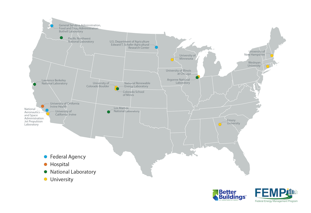
The Smart Labs Accelerator, run from 2017-2020, was an initiative by DOE's Federal Energy Management Program (FEMP) and Better Buildings Initiative to work with laboratory facilities looking to push the boundaries of smart, efficient laboratory operation and design best practices. Through the Accelerator, DOE worked with universities, federal agencies, national laboratories, and hospitals to advance strategies that rapidly improve energy efficiency in laboratory buildings.
Over the 3-year Accelerator period, partners implemented a series of low- and no-cost energy efficiency measures for a short-term energy reduction target of at least 5% in one laboratory and established 10-year targets of at least 20% across their portfolio of laboratory buildings. Partners worked together to develop standardized approaches to overcoming common barriers to energy efficiency in laboratories, such as insufficient energy performance measurement methods and resistance to implementing efficient operational procedures. Better Buildings worked with partners to document model approaches to reduce energy consumption that include operational changes, technological upgrades, and strategic energy management approaches.
The dedication and innovation of successful partners is the driving success behind the Smart Labs Toolkit, and the best practices developed over the course of the Accelerator are incorporated as highlighted case studies.
Accelerator Partners included:
- Argonne National Laboratory
- Colorado School of Mines
- Emory University
- General Services Administration Food and Drug Administration Bothell Laboratory
- Lawrence Berkley National Laboratory
- Los Alamos National Laboratory
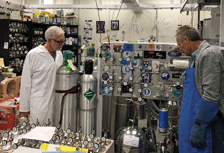
- National Aeronautics and Space Administration Jet Propulsion Laboratory
- National Laboratory of the Rockies
- Pacific Northwest National Laboratory
- U.S. Department of Agriculture Edward T. Schafer Agricultural Research Center
- University of California Irvine
- University of California Irvine Health
- University of Colorado Boulder
- University of Illinois Chicago
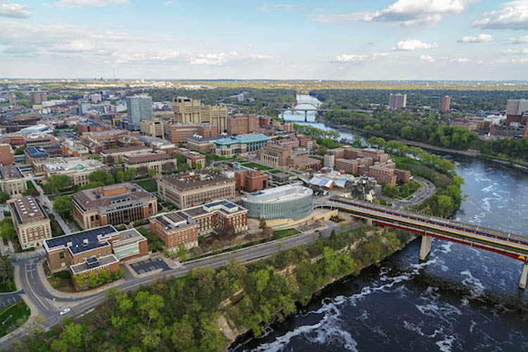
- University of Minnesota
- University of New Hampshire
- Wesleyan University
Case Studies
A Decade of Smart Labs Experience: University of California, Irvine
University of California, Irvine
Photo credit: UCI

Driving Energy Savings Through Occupant Engagement and Behavior Change
Colorado School of Mines
Photo credit: Colorado School of Mines

Identifying Smart Lab Opportunities at Pacific Northwest National Laboratory
Pacific Northwest National Laboratory
Photo Credit: PNNL
University of Illinois at Chicago
Photo credit: NLR
Lawrence Berkeley National Laboratory

U.S. Department of Health and Human Services Center for Disease Control and Prevention
University of California Irvine Smart Labs Workshop With Design-Build Add-On
University of California, Irvine
Photo credit: UCI
The Critical Role of a Lab Ventilation Management Program Coordinator
Los Alamos National Laboratory
Photo credit: NLR

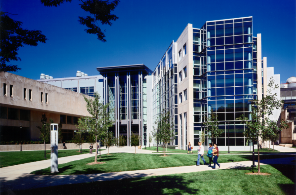
University of Colorado Boulder
Photo credit: LBNL

Argonne National Laboratory
Photo Credit: ANL

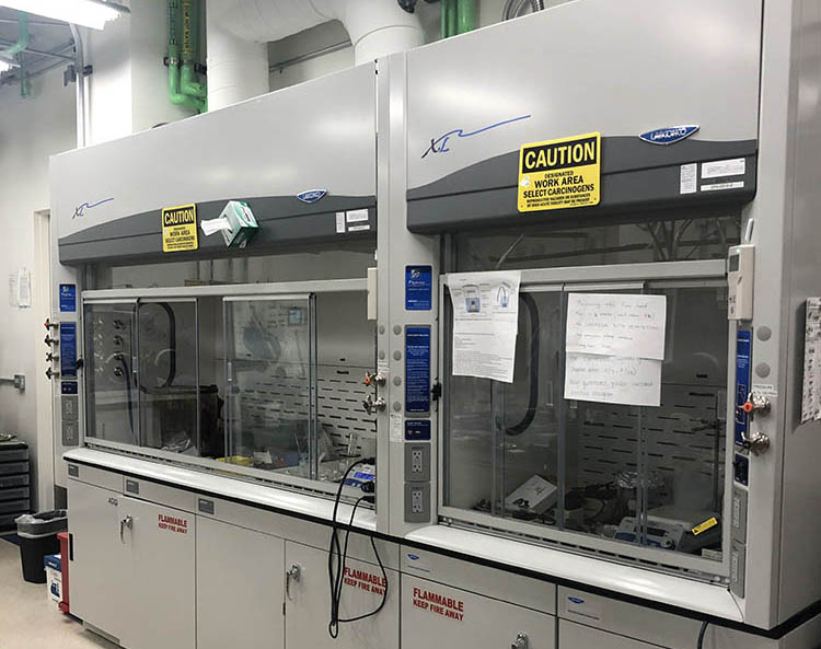
In-house Fume Hood Testing Ensures Safety and Savings
National Laboratory of the Rockies
Photo Credit: NLR
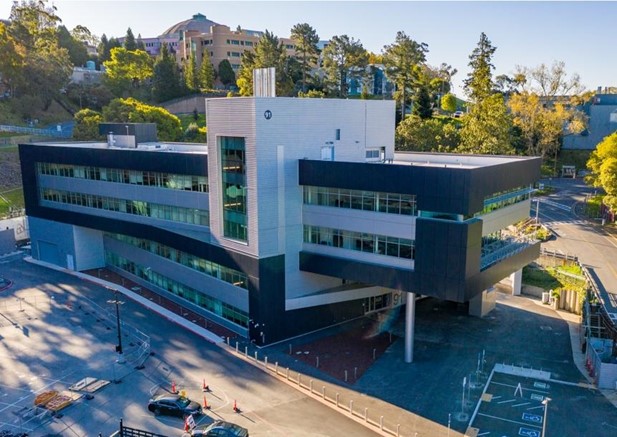
Lawrence Berkeley National Laboratory Efficiently Energizes their Integrative Genomics Building
Lawrence Berkeley National Laboratory
Photo Credit: LBNL
University of Chicago
Photo Credit: University of Chicago
Optimizing Laboratory Ventilation with Computational Fluid Dynamics
Colorado, USA
Photo Credit: CPP Wind Consultants
From Airflow to Innovation: A Laboratory Ventilation Risk Assessment in Action
University
Photo Credit: NLR
Codes, Standards, Laws, and Regulations
This guideline serves as a resource to help facilities implement projects to improve performance of laboratories and critical control environments. Elements of this guide can be implemented in the absence of, or as a supplement to, respective laws and regulations, standards developed by authoritative bodies, and site-specific protocols. Where national or local laws require a higher (specific or additional) standard, they must be followed. Where national or local laws require less stringent standards, the facility guidelines and standards shall be followed.
System design and operating requirements must comply with mandatory provisions of related codes and standards, unless quantitative testing shows safety standards are adequately met and a waiver is granted. Nothing in this guide is intended to supersede requirements in codes and standards, the requirements of the authority having jurisdiction, or to replace the need to consult with registered design professionals, code official, and site EH&S staff.
Ventilation Code Requirements
Summary of Codes and Standards
| Code / Standard | Ventilation Rates | Comments | ||
|---|---|---|---|---|
| Occupied | Unoccupied | |||
| ACGIH | None Specified | None Specified | Based on Specifics of the Hazard and Environment | |
| IMC | 1 cfm/ft2 | 1.7 ACH | ||
| NFPA 45 | 6+ ACH | 4 ACH | ||
| NRC, Prudent Practices | 6 to 12 ACH | None Specified | ||
| 29 CFR 1910.1450, Appendix A | None Specified | None Specified | Refers chemical hygiene plan developers to Prudent Practices for occupied ventilation rates. Continuous Ventilation is Appropriate. | |
| ANSI Z9.5 | None Specified | None Specified | Ventilation rates depend on a number of concerns, and this standard recommends a hazard evaluation or risk assessment to determine the minimum flow. See below for more information. References ASHRAE 62.1 |
|
| ASHRAE 62.1 | 1 cfm/ft2 | 1.7 ACH | ASHRAE 62.1 & IMC require 1 cfm/SF of exhaust not 6 ACH. | |
| ASHRAE Committee 9.10 | LVDL-0 | ASHRAE 62.1 | ASHRAE 62.1 | See Standard for Definitions of each LVDL |
| LVDL-1 | ASHRAE 62.1 | ASHRAE 62.1 | ||
| LVDL-2 | 4-6 ACH | ASHRAE 62.1 | ||
| LVDL-3 | 6+ ACH | 4 ACH | ||
| LVDL-4 | 8+ ACH | 4 ACH | ||
ACGIH: Industrial Ventilation: A Manual of Recommended Practice
Paragraph 10.6, Airflow Rate, states:
Specific quantities of minimum outdoor air supply may be obtained from building and health codes or from criteria developed by groups such as ASHRAE.
Paragraph 10.6.1, Air Changes, states:
Air changes per hour or air changes per minute is a poor basis for ventilation criteria. The required ventilation depends on the generation rate and toxicity of the contaminant, not on the size of the room in which it occurs.
International Mechanical Code (IMC)
Chapter 4, Ventilation, paragraph 401.2 states:
Ventilation Required. Every occupied space shall be ventilated by natural means in accordance with Section 402 or by mechanical means in accordance with Section 403.
Table 403.3.1.1 identifies minimum ventilation rates for various space types based upon occupancy and space area, with similar requirements as those identified in ASHRAE 62.1. For a typical laboratory with a 10-foot ceiling, the IMC required exhaust flow rate results in an air change rate of 6 ACH occupied, 1.7 ACH unoccupied.
NFPA 45: Standards on Fire Protection for Laboratories using Chemicals
Air change rate requirements and/or recommendations are not specifically defined in the main body of NFPA 45, with only a general requirement that "Laboratory units and laboratory hoods in which chemicals are present shall be continuously ventilated under normal operating conditions" included in Chapter 7, Laboratory Ventilation Systems and Hood Requirements, paragraph 7.2.2.
The non-mandatory Appendix A, paragraph 7.2.2 states:
A minimum ventilation rate for unoccupied laboratories (e.g., nights and weekends) can be as low as 4 room air changes per hour with proper laboratory operations and storage of chemicals. Occupied laboratories typically operate at rates greater than 6 air changes per hour, consistent with the conditions for use for the laboratory. Occupied laboratories should determine their supply airflow rates based on cooling requirements, amount of exhaust air required for the hoods, or exhaust devices in the laboratory, whichever is greatest. Use of only an "air change per hour" criteria is not considered proper design. Adequate ventilation shall be provided to ensure occupant safety and safe operation of exhaust devices used inside the laboratory.
Laboratory ventilation operating at lower rates should employ specific measures to monitor for potentially hazardous conditions and increase the ventilation automatically upon detection of any condition within 25 percent of the level of concern. If such a monitoring system is used, it should be fail-safe and be of such a nature that it will detect all potential leakage throughout the entire laboratory area. These systems should be reserved for locations where the anticipated contaminants can be measured reliably and activate the control system within a sufficiently rapid time period to provide occupant protection. In the event of a failure of the monitoring system or control components, the ventilation system should return to the designated occupied ventilation rate. Detailed analyses of flow paths, dead pockets, and failure modes under all credible scenarios should be performed to avoid exposure.
National Research Council: Prudent Practices in the Laboratories
Paragraph 9.C.4 states:
A general ventilation system that gives 6 to 12 room changes per hour is normally adequate. More airflow may be required to cool laboratories with high internal heat loads.
29 CFR 1910.1450, Appendix A: "National Research Council Recommendations Concerning Chemical Hygiene in Laboratories" (Non-Mandatory)
Recommendations from section titled "Prudent Practices in the Laboratory, Handling and Management of Chemicals" The Occupational Safety and Health Administration (OSHA) indicates that "Prudent Practice" should be consulted "for a more extended presentation and justification for each recommendation."
Section A.4, "Provide Laboratory Ventilation" 29 CFR 1910.1450 states:
A laboratory ventilation system should include the following characteristics and practices:
- Heating and cooling should be adequate for the comfort of workers and operation of equipment. Before modification of any building HVAC, the impact on laboratory or hood ventilation should be considered, as well as how laboratory ventilation changes may affect the building HVAC.
- A negative pressure differential should exist between the amount of air exhausted from the laboratory and the amount supplied to the laboratory to prevent uncontrolled chemical vapors from leaving the laboratory.
- Local exhaust ventilation devices should be appropriate to the materials and operations in the laboratory.
- The air in chemical laboratories should be continuously replaced so that concentrations of odoriferous or toxic substances do not increase during the workday.
- Laboratory air should not be recirculated but exhausted directly outdoors.
- Air pressure should be negative with respect to the rest of the building. Local capture equipment and systems should be designed only by an experienced engineer or industrial hygienist.
- Ventilation systems should be inspected and maintained on a regular basis. There should be no areas where air remains static or areas that have unusually high airflow velocities.
ANSI/AIHA Z9.5: Laboratory Ventilation
ANSI Z9.5 does not identify a specific air change rate. Rather, this standard recommends a hazard evaluation or risk assessment to determine the minimum flow.
From section 2.1.2 Laboratory (Room) Ventilation Rate
An air exchange rate (air changes per hour) cannot be specified that will meet all conditions.
Furthermore, air changes per hour is not the appropriate concept for designing contaminant control systems. Excessive airflow with no demonstrable safety benefit other than meeting an arbitrary air change rate can waste considerable energy.
ANSI Z9.5-2012 indicates typical occupied ventilation rates of 4 - 10 ACH.
It also discusses supply and exhaust air strategies. The discussion related to paragraph 5.3.1, Supply Air Volume, indicates:
The ventilation rate selected for a laboratory depends on the following concerns:
- control of thermal and psychrometric environment (ASHRAE Laboratory Design Guide),
- dilution and displacement of contaminants not captured by exposure control devices,
- effective operation of exposure control devices, such as laboratory hoods (See Sections 3 and 4), and
- space pressurization (see Section 5.2.1)
The quantity of dilution (or displacement) ventilation required is a subject of controversy. Numerous studies make it clear that the air flow rate is just one factor affection contaminant levels in the room. Frequently, other factors have been shown to make a bigger difference than some changes in the air flow rates. These factors include mechanical arrangement of the supply and exhaust devices, thermal effects, occupant movement and the motion and location of doors.
These studies do not show that the flow rate does not matter. On the contrary, they have shown that the flow rate certainly does affect contamination levels, but that there is no air change rate that is always appropriate.
Usually, a laboratory ventilation system surpasses the codes and standards that apply to the building in general. For example, the OA ventilation per person usually exceeds the requirements of ASHRAE Standard 62.1.
ASHRAE 62.1: Ventilation for Acceptable Indoor Air Quality
ASHRAE 62.1 is similar to the IMC in that it has a procedure to follow to determine the minimum mechanical outdoor air and exhaust air required. Table 3.2.2.1, Minimum Ventilation Rates in Breathing Zones is very similar to the equivalent IMC table. The values for science laboratory outdoor air and exhaust are identical to the IMC. Therefore, for typical laboratories with a 10 foot ceiling, ASHRAE 62.1 requires an air change rate of 6 per hour occupied and 1.7 unoccupied.
ASHRAE, Committee 9.10, Classification of Laboratory Ventilation Design Levels
This ASHRAE standard provides an in-depth look at deploying effective ventilation measures to maintain safe workspaces and guides design engineers, users, and facility operators to understand appropriate laboratory air control systems (LACS). For example:
The laboratory and the LACS must be appropriate for the chemical hazards and capable of providing adequate control and protection when properly designed, operating, and used by trained personnel. The level of risk and the demand for ventilation can vary between laboratories and with any laboratory over time depending on the occupants, the types of hazards, and the processes conducted. For this reason, management of change procedures are particularly important in a laboratory setting. A successful management of change program involves a variety of stakeholders, but the design basis of the laboratory ventilation system should include consideration of how to support changes in the laboratory practices over time.
This standard defines 5 different laboratory ventilation design levels (LVDLs) and prescribes a suggested level of control for air change rates and other design features.
Emergency System Code Requirements
Refer to local code requirements as a priority, but here are national and international code requirements for emergency systems in labs to help understand requirements.
NFPA 70®: National Electric Code (NEC)
The NFPA 70 National Electric Code, Article 700 Emergency Systems 700.12 states:
(B) Generator Set.
(1) Prime Mover-Driven. For a generator set driven by a prime mover acceptable to the authority having jurisdiction and sized in accordance with 700.4, means shall be provided for automatically starting the prime mover on failure of the normal service and for automatic transfer and operation of all required electrical circuits. A time-delay feature permitting a 15-minute setting shall be provided to avoid retransfer in case of short-time reestablishment of the normal source.
(2) Internal Combustion Engines as Prime Movers. Where internal combustion engines are used as the prime mover, an on-site fuel supply shall be provided with an on-premises fuel supply sufficient for not less than 2 hours' full-demand operation of the system. Where power is needed for the operation of the fuel transfer pumps to deliver fuel to a generator set day tank, this pump shall be connected to the emergency power system.
International Building Code (IBC): Fuel Requirements
The International Building Code (IBC) also provides another source on fuel requirements. The reference to standby power relates to legally required standby and not optional standby power.
Installation. Emergency power systems and standby power systems shall comply with Sections 2702.1.1 through 2702.1.7.
Load transfer. Emergency power systems shall automatically provide secondary power within 10 seconds after primary power is lost, unless specified otherwise in this code. Standby power systems shall automatically provide secondary power within 60 seconds after primary power is lost, unless specified otherwise in this code.
Load duration. Emergency power systems and standby power systems shall be designed to provide the required power for a minimum duration of 2 hours without being refueled or recharged, unless specified otherwise in this code.
Acronyms
| Acronym | Definition |
|---|---|
| ACH | air changes per hour |
| ACS GCI | American Chemical Society Green Chemistry Institute |
| ACT | accountability, consistency, and transparency |
| AIA | American Institute of Architects |
| ANSI | American National Standards Institute |
| ASSP | American Society of Safety Professionals |
| BAS | building automation system |
| BETR | Bringing Efficiency to Research |
| BMP | Building Management Plan |
| CAV | constant air volume |
| CFM | cubic feet per minute |
| CU | University of Colorado |
| Cx | commissioning |
| DCV | demand control ventilation |
| DSIRE | Database of State Incentives for Renewables & Efficiency |
| ECD | exposure control device |
| EH&S | Environmental Health and Safety |
| EPA | United States Environmental Protection Agency |
| ESCO | energy service company |
| ESPC | energy savings performance contract |
| gal | gallon |
| FEMA | Federal Emergency Management Agency |
| HVAC | heating, ventilating, and air conditioning |
| I2SL | International Institute for Sustainable Laboratories |
| IT | information technology |
| kBTU | kilo-British thermal unit |
| kWh | kilowatt hour |
| LED | light-emitting diode |
| LEED | Leadership in Energy and Environmental Design |
| LVMP | Laboratory Ventilation Management Program |
| LVRA | Laboratory Ventilation Risk Assessment |
| MAQ | maximum allowable quantity |
| NFPA | National Fire Protection Association |
| O&M | operations and maintenance |
| OSHA | Occupational Safety and Health Administration |
| PPA | power purchase agreement |
| PPE | personal protective equipment |
| ppm | parts per million |
| RCB | risk control band |
| REC | renewable energy credit |
| ft2 | square foot |
| SOP | standard operating procedure |
| SPP | simple payback period |
| SREC | solar renewable energy credit |
| TAB | testing, adjustment, and balancing |
| UAG | University Alliance Group |
| UC | University of California |
| UCI | University of California, Irvine |
| UCLA | University of California, Los Angeles |
| UESC | utility energy savings contract |
| ULT | ultra-low temperature |
| VAV | variable air volume |
| W | Watt |
| ZEB | zero energy building |
Attachments
Introduction
Calculators, Tools, and Templates
Best Practice Guides and Manuals
Research Papers and Articles
- Definition of a "Zero Net Energy" Community
- Zero Energy University Campuses: A 2018 Progress Update on Reaching Campus Energy Goals
- Zero-Energy Buildings: A Critical Look at the Definition
- My Green Lab: The Carbon Impact of Biotech and Pharma
- The United Kingdom Science Park Association Breakthrough Issue 14: Lab Innovations November 2021 (pg. 62–63)
Training, Conferences, and Webinars
Plan
Training, Conferences, and Webinars
- Better Buildings: Partner Insider Talk with Wendell Brase of UCI
- Harvard Green Labs Summit Keynote
- Laboratory Benchmarking Tool Training
Best Practice Guides and Manuals
- I2SL Best Practices Guide: Benchmarking Energy Efficiency in Laboratories
- I2SL Best Practices Guide: Energy Efficiency Projects and Principal Investigators
Calculators, Tools, and Templates
- Laboratory Benchmarking Tool
- Smart Labs checklist developed by Pacific Northwest National Laboratory
- Smart Labs Roadmap Planning Template
Research Studies and Papers
Assess
Best Practice Guides and Manuals
- ASHRAE Laboratory Design Guide
- I2SL Best Practices Guide: Energy Savings with Demand Based Control
- I2SL Best Practices Guide: Laboratory Water Efficiency
- I2SL Best Practice Guide: Water Efficiency Guide for Laboratories
- I2SL Laboratory Modeling Guideline Using ASHRAE 90.1-2019 APPENDIX G
- SEFA Selection and Management of Exposure Control Devices in Laboratories
- Strengthening the Disaster Resilience of the Academic Biomedical Research Community: Protecting the Nation's Investment
- Water Sense at Work: Best Management Practices for Commercial and Institutional Facilities
- Laboratory Environmental Test guide
- System Operating Mode Test guide
- Laboratory Resilience
- Design and Operating Sustainable Laboratory Exhaust Systems
- Manifolding Laboratory Exhaust Systems
Calculators, Tools, and Templates
- Ventilation
- Water
- Energy
- Resilience
Codes and Standards (may require purchase)
- ANSI/AIHA/ASSP Z9.5-2012 – Laboratory Ventilation
- ANSI/ASHRAE Standard 62.1-2019 – Ventilation for Acceptable Indoor Air Quality
- ASHRAE Classification of Laboratory Design Levels
- ASHRAE Handbook – HVAC Applications
- ASHRAE Procedures for Commercial Building Energy Audits
- OSHA 29 CFR 1910.1450
Example Documents
- NLR Dispersion Modeling Engineering Report – Energy Systems Integration Facility
- Safety Data Sheet from Sigma-Aldrich on Dichloromethane
- University of California, Irvine: Detailed Project Plan for Building 55
- University of California, Irvine: Detailed Project Program for Medical Sciences "B" and "D" Major Building Maintenance
- University of California, Irvine: Technical Proposal for Building 55
- University of California, Irvine: Technical Proposal for Medical Sciences "B" and "D" Major Building Maintenance
Optimize
Best Practice Guides and Manuals
- Overview of Financing in the Higher Education Sector
- Energy Savings Performance Contracts for Federal Agencies
- Utility Program and Utility Energy Service Contracts for Federal Agencies
- Federal On-Site Renewable Power Purchase Agreements
- BETR Grants
- Energy and Project Procurement Development Services
- I2SL Technical Bulletin: Retro-Commissioning Laboratories for Energy Efficiency
- I2SL Best Practices Guide: Building Automation Systems in Laboratory Environments
- ENERGY STAR Retrocommissioning
Calculators, Tools, and Templates
- U.S. Department of Energy ESCO Selector Tool
- Better Buildings Financing Navigator
- Better Buildings ESPC Toolkit
- DSIRE: Database of State Incentives for Renewables & Efficiency®
- Better Buildings ESPC Toolkit
- I2SL Laboratory Benchmarking Tool
Example Documents and Showcase Projects
- University of Colorado Boulder Financial Incentives for Energy- and Water Efficient Equipment
- Better Buildings Smart Labs Initiative Showcase Project: UC Irvine Natural Sciences II
- Data Analytics for Operations at Berkeley Lab
- Berkeley Lab Ongoing Commissioning
- University of New Hampshire Planning, Design, and Construction Guidelines
- Sustainable Labs Program at University of Virginia
Training, Conference, and Webinars
Manage
Best Practice Guides and Manuals
- FEMA Guidelines for Continuity of Operations Plan
- Stanford University Laboratory Ventilation Management Program
- Cornell University Laboratory Ventilation Management Program
Calculators, Tools, and Templates
- I2SL Laboratory Benchmarking Tool
- Project Haystack
- Building Management Plan
- Sample Project Management and Test Schedule Flow Chart
Codes and Standards
New Construction
Best Practice Guides and Manuals
Calculators, Tools, and Templates
Working Scientists
Best Practice Guides and Manuals
- American Chemical Society
- University of York
- 12 Principles of Green Chemistry
- Guide to Green Chemistry Experiments for Undergraduate Organic Chemistry Laboratories
- ACS GCI Pharmaceutical Roundtable Solvent Selection Guide
- University of Michigan
- OSHA
- Blog post: Tips to Maximize Success in A Shut the Stash Competition
- Fume Hood Sash Management Campaign Implementation Guide
- ASHRAE Procedures for Commercial Building Energy Audits
- Better Buildings Plug and Process Loads
- Ultra-low Temperature Freezer User Guide
- freezerchallenge.org
- Reducing the Risk of Mercury Exposure for a Sustainable Future
- My Green Lab ACT Label General Information
- My Green Lab ACT website
- How to Conduct a Lab Space Evaluation
Calculators, Tools, and Templates
- DOZN Tool
- Green Chemistry Alternatives Wizard
- Energy Audit Data Collection Form
- Energy Star Lab Grade Refrigerators and Freezers
- Sustainable Facilities Tool Plug Load Control
- ACT Database of Product Information
Training, Conference, and Webinars
- My Green Lab
- My Green Lab Episode 1 - Activation Energy
- My Green Lab Episode 2 - Rachel Goes Dumpster Diving
- My Green Lab Episode 3 - Water, Water Everywhere
- My Green Lab Episode 4 - The Lab Bonds
- My Green Lab Ambassador Program
- Reducing Campus ACH Safely
- UC Irvine Smart Labs Workshop
- Laboratory Lighting Controls Upgrade
Articles, Research Studies, and Papers
- Getting Below Six Air Changes
- Ultra-Low Temperature Freezers Specification
- Field Demonstration of High-Efficiency Ultra-Low-Temperature Laboratory Freezers
- Mercury Free Microscopy: An Opportunity for Core Facility Directors
- Removing Mercury from Microscopy
- Harvard's Mercury-Free Microscopy initiative
Additional Resources
Best Practice Guides and Manuals
- Better Buildings: Energy Management Information Systems
- Council on Environmental Quality: Federal Sustainability Plan
- DOE Energy Saver: Electric Resistance Heating
- DOE Grid-interactive Efficient Buildings 2020 Projects Summary
- EPA GHG Development Process & Guidance
- EPA Scope 1 and Scope 2 Inventory Guidance
- EPA Scope 3 Inventory Guidance Sheets
- GHG Protocol Scope 2 Guidance
- Greenhouse Gas Protocol Corporate Accounting and Reporting Standard
- I2SL Best Practices Guide: Energy Recovery in Laboratory Facilities
- NEEP: Guidance and Metrics for Implementing Decarbonization Policies
- New Buildings Institute: Getting to Zero Insider's Guide on Carbon Neutral Buildings
- NLR Energy Storage Research
- NLR Roadmap to Decarbonization
- Second Nature: Carbon Neutral Colleges and Universities
Calculators, Tools, and Templates
- AASHE: The Sustainability Tracking, Assessment & Rating System (STAR)
- ANL VISION Model
- Better Buildings Low Carbon Strategies Toolkit
- Cost of Renewable Energy Spreadsheet Tool
- EIA Hourly Electric Grid Monitor
- ENERGY STAR Scope 3 Use of Sold Products Analysis Tool (Excel)
- EPA eGrid: Power Profiler
- EPA eGrid: Web Map for Power Plants Across U.S.
- EPA Greenhouse Gas Equivalencies Calculator
- EPA Market Instruments
- EPA Simplified GHG Emissions Calculator
- Fleet Procurement Analysis Tool
- Future Automotive Systems Technology Simulator
- GHG Protocol Scope 3 Evaluator
- Greenhouse Gas Inventory and Tracking in Portfolio Manager
- HVAC Resource Map
- NLR PVWatts Calculator
- NLR REopt Tool
- NLR System Advisor Model
- The Climate Explorer: Climate Projection Charts for U.S. Counties
- U.S. Green Building Council: LEED Tools
Training, Conference, and Webinars
- Decarbonization Considerations: Performance Contracting Webinar
- EIA: How much carbon dioxide is produced when different fuels are burned?
- EIA: What are the greenhouse gases and air pollutant emissions factors for fuels and efficiency?
- FEMP Electric Vehicle Training Courses
- I2SL Best Practices Guide: Laboratory Water Efficiency
Articles, Research Studies, and Papers
- Better Buildings Solution Center: Decarbonization Resources Hub
- EIA Today in Energy: Average Hourly Electricity Load During Typical Day by Region
- Existing and Potential Corporate Off-Site Renewable Procurement in the Southeast
- NLR Cambium Emission Data Sheets
- NLR Energy Storage Research website
- U.S. Global Change Research Program
References and Resources
- ACGIH®: Industrial Ventilation: A Manual of Recommended Practice for Design, 27th Edition. Cincinnati, Ohio: American Conference of Governmental Industrial Hygienists, 2010.
- ACGIH®: Threshold Limit Values (TLV®) for Chemical Substances and Physical Agents. Cincinnati, Ohio: American Conference of Governmental Industrial Hygienists, 2002.
- American Conference of Governmental Industrial Hygienists (ACGIH). 2010. Industrial Ventilation: A Manual of Recommended Practice for Design, 27th Edition. Cincinnati, Ohio.
- ANSI/AIHA Z9.5, American National Standard for Laboratory Ventilation
- ANSI Z9.5-2012: Manning, et. al 2000, ASHRAE Transactions, DA-0014-3: Analysis of Air Supply Type and Exhaust Location in Laboratory Animal Research Facilities Using CFD
- ANSI Z9.5-2012: Klein, et. al 2009, JCHAS, Laboratory air quality and room ventilation rates
Smith and Yancey-Smit, 2009, JCHAS, Specification of Airflow Rates in Laboratories) - ANSI/ASHRAE 41.2-1987 (RA 92): Standard Methods for Laboratory Air Flow Measurement. Atlanta, Ga.: American Society of Heating, Refrigerating and Air Conditioning Engineers, 1992.
- ANSI/ASHRAE 41.3-1989: Standard Method for Pressure Measurement. Atlanta, Ga.: American Society of Heating, Refrigerating and Air Conditioning Engineers, 1989.
- ANSI/ASHRAE 41.7-1984 (RA 00): Method of Test Measurement of Flow of Gas. Atlanta, Ga.: American Society of Heating, Refrigerating and Air Conditioning Engineers, 2000.
- ANSI/ASHRAE 110-1995: Method of Testing Performance of Laboratory Fume Hoods. Atlanta, Ga.: American Society of Heating, Refrigerating and Air Conditioning Engineers, 1995.
- ASHRAE 90.1 Energy Standard for Buildings Except Low-Rise Residential Buildings
- ASHRAE 62, Ventilation for Acceptable Indoor Air Quality
- ASHRAE Handbook HVAC Applications.
- ASHRAE Lab Design Guide, 2016.
- Laboratories for the 21st Century, Best Practice Guide Optimizing Laboratory Ventilation Rates, Draft, September 2008, Pg 1.
- NFPA 45, Fire Protection for Laboratories Using Chemicals
- SEFA, Laboratory Fume Hoods, Recommended Practices
- SMACNA: HVAC Duct Construction Standards: Metal and Flexible, Merrifield, Va.: Sheet Metal and Air Conditioning Contractors' National Association, 1995.
- Smith, T.C. and Yancey-Smith, S.L: "Specifying Airflow Rates for Laboratories.", Journal of Chemical Health and Safety 16(5): September/October 2009.
- Smith, T.C., and Crooks, S.M.: "Implementing a Laboratory Ventilation Management Program." Journal of Chemical Health and Safety 3(2):12–16 (1996).
- Smith, T.C.: "The Unintended Practice of Using Employee Health as an Indicator of Proper Hood Performance", Journal of Chemical Health and Safety, January/February, 2004.
- Heinsohn, Robert J., Industrial Ventilation Engineering Principles, University Park, PA 1991;
- Diberardinis, Louis J., Guidelines for Laboratory Design, 2nd ed, 1993; pg 100.
- Public Works and Government Services Canada, MD 15127 – 2016: Laboratory Energy and Safety Optimization Process (Lab ESOP).